Reduce Cost. Accelerate Scalability.
We help companies design and manufacture the most complex capital equipment in the world.
Personalized Time To Market Services™

Cost Modeling


Your Technology. Our Proven Process.
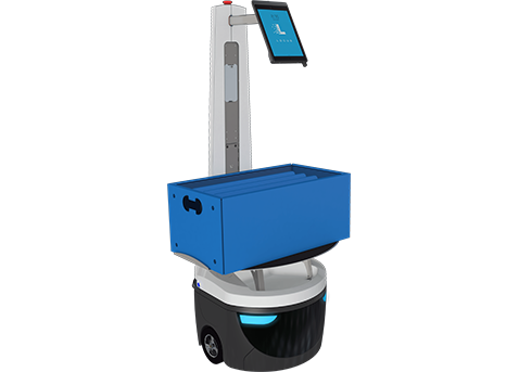
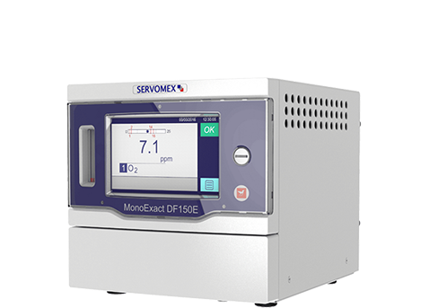
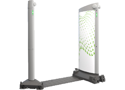
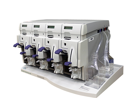
Supporting industries including robotics and automation, semiconductor, security, medical, life sciences, food service, energy, and additive manufacturing.
Much More Than a “Contract Manufacturer”
Scaled Product Launch™
Our Proprietary SPL™ Process
A well-documented phase gate approach to successful new product introduction that focuses on speed, cost reduction, second sourcing, and build efficiency with intense collaboration.
- Elimination of Tribal Knowledge
- Documentation Verification & Validation
- Serialization & Traceability Assessment
- Overall Acceleration of Scalability
Strategically Integrated
Vertically Integrated, Where it Matters
In-house printed circuit board assembly (PCBA) ensures quality and control over a critical piece of the manufacturing process, accelerating time-to-market and eliminating delays and margin stack.
- Design and Layout Services
- 24/7 High Speed Line Availability
- AOI, Flying Probe, In-Circuit Test, 3D X-Ray
- Lot 4 Traceability & Silicon Expert™
Global Supply Chain
The Most Advanced Supply Chain Imaginable
We combine forward thinking experts, innovative software tools, transparent communication, and trusted partners to find the highest quality components balancing cost, lead time and delivery flexibility.
- Global Buying Leverage
- Long Standing Trusted Relationships
- Unmatched Flexibility
Infinite Capacity™
Never Miss a Market Opportunity™
Our commitment to providing the resources, facilities and equipment to handle unthinkable and unpredictable market demand, enabling you to say YES to every market opportunity.
- 24/7 Production Availability
- Finished Goods Storage & Distribution
- Aftermarket & Refurbishment Services
Compliance & Certifications
Process and Results that Meet or Exceed All Expectations
Commercialize products compliantly with all applicable standards, statutory, and regulatory requirements. We have unmatched experience working with a range of regulatory agencies including CSA, CE, TUV, and IEC.
At the end of the day, what we really build is TRUST.

